
The stepper motor is a motor that rotates in steps, unlike regular AC or DC motor that rotates continuously.
The stepper motor is expressed in terms of step size, for example, if a stepper motor specifies that the step size of 10 degrees, then it means that every step of the stepper motor is 10 degrees.
Here we will discuss about the unipolar stepper motor, before you start looking in the unipolar stepper motors, we will briefly discuss the different types of stepper motors:
1. Unipolar stepper motor
2. Bipolar stepper motor
These are usually available on the market, along with this we also have other types of stepper motors like multiphase steppers, etc., that are behind the scope of this article.
In general, the control of a unipolar stepper motor is simple because it is easy to control the current phase of each winding of stepper motor and you can observe the stepper motor rotating in one direction. But when it comes to bipolar stepper motor, you need to change the direction of current for each step. In other words, the current passing through each winging of the stepper motor will alternate for each step, is rotated by the stepper motor in one direction.
Now when it comes to control a unipolar stepper motor, first we must understand the internal circuitry of unipolar stepper motor.
I named each phase coils of Phase A, B, C and E with a common cable, this designation is not a rule, It just for an easy understanding of the circuit.
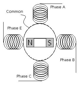
From the figure above, it’s clear that the stepper motor will have a minimum of 5 wires. Sometimes it can even be 6 wires in which there are two common wires. We just have to short the two common wires and take them as a common wire.
Now, using a common wire and the phase wire, you can rotate the stepping motor by supplying a source of voltage. As the power of each phase in sequence one after another, you can observe the stepper motor rotating in one direction.
For example, if you have a stepper motor with a step size of 10 degrees, then you have 360/10 = 36 steps to a complete revolution for the shaft of the stepper motor. This means you need to fire each phase separately one after another in a sequence of 36 times.
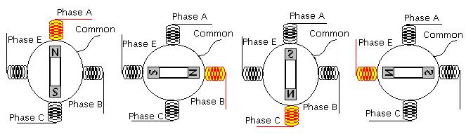
Step 1: Phase A Energize
Step 2: Phase B Energize
Step 3: Phase C Energize
Step 4: Phase E Energize
Step 5: Phase A Energize
Step 6: Phase B Energize
Step 7: .. ... ............
.... ... ......
.... ... ......
.... ... ......So on to step 36
Step 36: Phase E Energize
When finally complete the step 36, the shaft of the stepper motor has completed 360 degrees of rotation. By altering the firing sequence you can turn the motor forward and backward.
The activation of a stepper motor phase is achieved by applying a voltage across the corresponding phase winding. For instance, to energize phase A using a 5 V DC supply, the positive terminal can be connected to the common wire and the negative terminal to the phase A wire. Although the polarity could theoretically be reversed, it is generally advisable to connect the common wire to the positive supply in practice. This approach aligns with the design of most commercially available integrated driver circuits, which are typically configured to sink current through the phase windings. Following this convention ensures compatibility with standard driving methods and simplifies circuit integration.